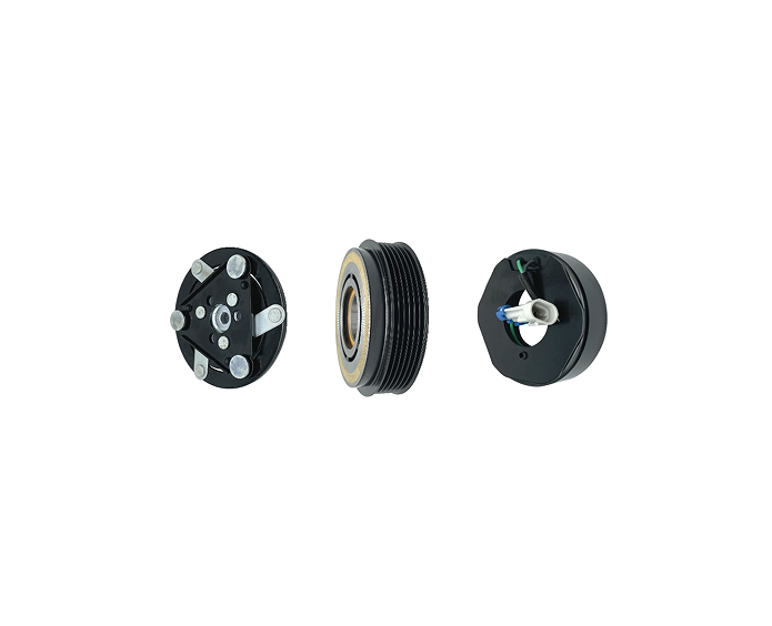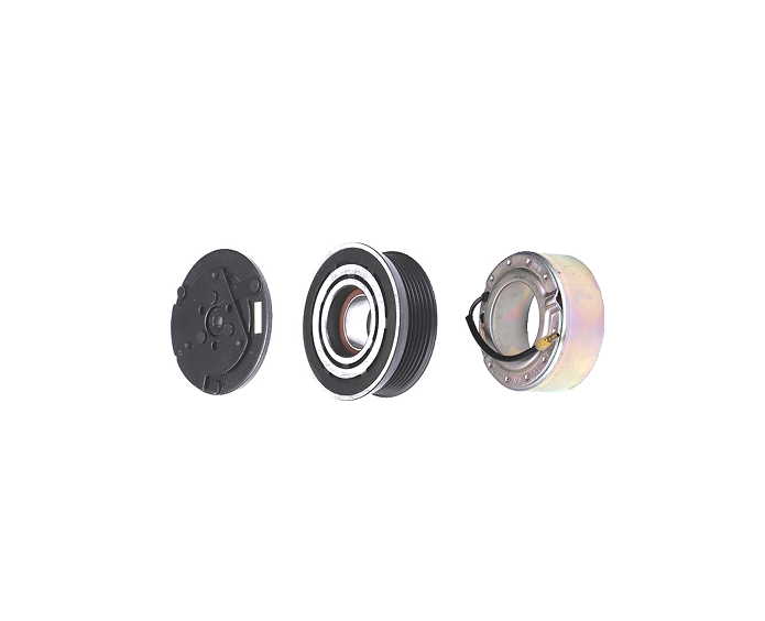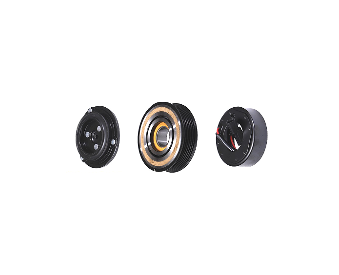

An automotive compressor control valve regulates the output of a compatible variable-displacement air-conditioning compressor. When the valve is sticking, leaking internally, electrically mismatched, contaminated, or simply the wrong reference, the vehicle can show low cooling, unstable vent temperature, excessive compressor load, or a fault that is incorrectly blamed on refrigerant charge. The correct replacement process is therefore not “find a valve that looks similar.” It is to confirm the compressor architecture, identify the valve interface, separate valve symptoms from system symptoms, test the old part and surrounding system, approve the replacement reference, and verify operation after installation.
This guide is written for automotive AC technicians, compressor rebuilders, aftermarket distributors, fleet maintenance teams, and buyers who need a controlled technical answer before ordering. It explains what the valve does, how it differs from an expansion valve or pressure sensor, which measurements matter, how to interpret common symptoms, what evidence to request from a supplier, and how to define a replacement without turning one vehicle-specific reference into a universal fitment claim.
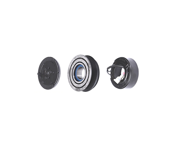
What Does an Automotive Compressor Control Valve Do?
An automotive compressor control valve adjusts compressor displacement or pressure response in a compressor designed for variable output. Instead of relying only on repeated clutch cycling, the vehicle control system can request more or less compressor work as cabin temperature, evaporator load, engine speed and system pressure change. The valve is one part of that control chain. It does not work as a stand-alone refrigeration regulator and it cannot correct an incorrect refrigerant charge, blocked circuit, damaged compressor or failed sensor.
In a typical belt-driven variable-displacement arrangement, the compressor is mechanically driven while the control valve responds to a pressure or electrical control condition defined by the compressor design. Depending on the architecture, the valve can influence crankcase pressure, swash-plate angle or another internal mechanism. The exact behavior differs by compressor family, which is why an electrical connector or body shape alone is not enough to prove interchangeability.
| Component | Primary role | Typical location | What a replacement must match |
|---|---|---|---|
| Compressor control valve | Controls compatible compressor displacement or pressure response. | Mounted in or on the compressor control circuit. | Compressor family, body, insertion depth, sealing, control method and application. |
| Expansion valve | Meters refrigerant into the evaporator. | At the evaporator or refrigeration circuit inlet. | Ports, sensing or actuator type, vehicle HVAC layout and refrigerant context. |
| Pressure switch or sensor | Measures or switches system pressure for protection or control. | Pressure line, receiver, manifold or designated port. | Thread, connector, pressure range, switching logic and application. |
| Compressor clutch | Engages or disengages mechanical drive on a belt-driven compressor. | Front of the compressor. | Pulley, bearing, coil, hub, connector, air gap and compressor mounting. |
The distinction matters during diagnosis and purchasing. A technician may see a pressure-related symptom and replace an expansion valve when the compressor control valve is not responding. A buyer may request an “AC valve” and receive a part designed for the evaporator. Put the component function, compressor model and old-part evidence in the enquiry before discussing price.
Which Compressor Systems Use a Control Valve?
Control valves are associated with compressor architectures that regulate output internally. The exact design may be described as variable displacement, variable capacity, electronically controlled, or pressure-controlled, depending on the manufacturer and market. A fixed-displacement compressor that uses simple clutch cycling may not accept the same valve, even if the housing and connector appear similar.
Before ordering, identify whether the compressor remains mechanically driven while displacement changes, whether the clutch cycles, and whether an electronic signal reaches the valve. Use the compressor label, original part number, vehicle service data, wiring information and old-part photographs. Do not infer the architecture from the vehicle model alone because a single model range can use more than one compressor supplier or HVAC specification.
Mechanical control and electrical control
Some valves respond primarily to pressure conditions generated inside the compressor. Others are electrically actuated or controlled by a variable signal from the vehicle HVAC module. A valve that is mechanically similar but has the wrong electrical characteristics can cause an underperforming compressor or a control fault. Conversely, a valve with the correct connector can still have the wrong internal calibration or flow behavior.
Why the compressor reference is the starting point
The compressor determines the valve seat, internal passage, control strategy, sealing arrangement and allowable response. The vehicle and engine information adds application context, but the compressor model and OE/OEM number should remain central in the matching record. If the compressor label is missing, photograph the compressor, mounting, connector and valve position, and provide the old component whenever possible.
How Is an Automotive Compressor Control Valve Different From an Expansion Valve?
A compressor control valve and an expansion valve both influence refrigeration performance, but they do so at different points in the system. The control valve affects compressor output. The expansion valve meters refrigerant into the evaporator. Their ports, installation positions, control signals and test methods are different. They should have separate catalogue families, inspection sheets and replacement instructions.
Kasen’s existing control valve versus expansion valve comparison provides the system-level distinction. For a technical replacement, the practical rule is simple: identify where the original part is installed and what component it controls before interpreting a cooling complaint.
| Diagnostic question | Control-valve direction | Expansion-valve direction |
|---|---|---|
| Where is the suspect part? | On or inside the compressor control circuit. | At the evaporator or refrigerant metering point. |
| What does it regulate? | Compressor displacement or pressure response. | Refrigerant flow into the evaporator. |
| What must match? | Compressor family, control signal, valve body and seal interface. | HVAC layout, ports, sensing or electronic actuator and application. |
| Typical evidence | Compressor identity, electrical or control data, pressure behavior and sample fit. | Port dimensions, sensing behavior, system pressures and evaporator application. |
Symptoms That May Point to a Control-Valve Problem
A control-valve fault can create symptoms that look like other air-conditioning problems. The valve should be considered only after basic system conditions have been checked. Low refrigerant, air or moisture in the circuit, a blocked filter, condenser airflow problems, a damaged compressor, an inaccurate pressure sensor, clutch slip, wiring damage or a restricted hose can produce similar results.
| Observed symptom | Possible control-valve link | Other causes to rule out |
|---|---|---|
| Cooling remains weak at idle and improves inconsistently with engine speed. | Valve may not regulate displacement as requested. | Charge level, condenser airflow, compressor wear, sensor input and belt drive. |
| Vent temperature changes repeatedly without a clear cabin-load reason. | Control response may be sticking or unstable. | Evaporator sensor, expansion valve, blower control, icing or refrigerant imbalance. |
| Compressor load is high or pressure response is abnormal. | Valve may remain in an incorrect displacement state. | Overcharge, restriction, oil issue, condenser problem or internal compressor damage. |
| Scan tool reports an actuator or pressure-control fault. | Valve circuit, connector or response may be outside the expected condition. | Harness, module, sensor, ground, reference voltage and software diagnosis. |
| Replacement valve leaks after installation. | Wrong seal, damaged seat, incorrect insertion or incompatible valve. | Debris, installation force, compressor seat damage or refrigerant circuit contamination. |
These symptoms are diagnostic directions, not proof. A responsible replacement decision records the operating conditions, pressure readings, control signal, compressor temperature, belt or clutch behavior and any fault codes. Replacing the valve without recording the baseline makes it difficult to know whether the valve solved the problem or whether another system fault remains.
Diagnostic Sequence Before Replacing the Valve
Use a repeatable sequence so that the valve is not blamed for a system failure that it did not cause. The sequence below is suitable for a workshop or technical buyer evaluating a returned compressor. Always follow the vehicle manufacturer’s service procedure and safe refrigerant-handling requirements.
- Confirm the complaint. Record ambient temperature, cabin temperature, vent temperature, engine speed, operating mode and whether the symptom appears at idle, cruise or both.
- Identify the compressor. Record the compressor manufacturer, model, OE/OEM number, vehicle, engine, production range and refrigerant or oil information available from service documentation.
- Check basic system conditions. Verify charge procedure, condenser airflow, belt or clutch operation, pressure readings, sensor data and visible leaks before removing the valve.
- Inspect the control circuit. Check the connector, pin retention, harness routing, corrosion, ground and control signal using the approved method for the vehicle.
- Compare valve identity. Photograph the original valve, body, connector, seals, retaining feature and markings. Measure critical dimensions if the part is removed.
- Inspect contamination and seat condition. Look for debris, damaged O-rings, burrs, corrosion or a compressor seat that could prevent correct valve travel or sealing.
- Test the replacement sample. Confirm fit, sealing, electrical behavior and the agreed functional or pressure-response check before releasing a batch.
- Verify the repaired system. Repeat the same operating conditions and document the result, not only the statement “air conditioner works.”
If the vehicle system has a diagnostic procedure for actuator commands or pressure-control response, use it. A generic resistance check cannot replace a system-level test when the vehicle expects a specific control behavior. Similarly, a valve that moves on a bench may not perform correctly if the compressor seat, sensor input or refrigerant condition is wrong.
Mechanical Matching Fields for a Replacement Valve
The mechanical interface determines whether the valve can be installed and sealed. Record the fields below on the technical drawing or inspection sheet. Where a value is unavailable, mark it as pending rather than copying a number from a similar reference.
| Field | What to inspect | Why it affects replacement risk |
|---|---|---|
| Body diameter and length | Measure at defined points with the correct tool. | Controls seating, insertion depth and surrounding clearance. |
| Insertion depth | Record shoulder-to-tip or reference surface distance. | Changes valve travel and internal control response. |
| O-ring groove and seal | Check groove geometry, seal size, material status and damage. | Controls leakage and insertion force. |
| Retainer or fixing method | Identify clip, screw, press fit, threaded feature or orientation. | Prevents movement, incorrect seating or service damage. |
| Connector and lead exit | Compare keying, pin count, retention and routing. | Protects electrical connection and prevents harness interference. |
| Valve tip or regulating element | Compare visible geometry and movement where accessible. | Similar bodies can contain different internal control elements. |
Take photographs with a scale or reference dimension, but do not use a photograph as the only dimensional record. A drawing or measured sample gives the supplier and buyer one common basis. When a valve is supplied with a seal kit, include the seal in the same approval because an otherwise correct valve can leak if the seal is wrong or damaged during installation.
Electrical and Control-Signal Checks
Electrical checks must follow the compressor and vehicle specification. A control valve may be driven by a variable signal, a current-controlled circuit or another architecture. The connector, pin assignment, resistance, current or duty-cycle information should be treated as reference-specific. Never assume that wire colors, pin positions or resistance values are universal across compressor brands.
Connector and harness
Inspect the connector key, lock, terminal condition, sealing and lead exit direction. A connector that plugs in loosely can create an intermittent fault. A replacement lead that exits toward the belt or hot exhaust surface can fail even when the valve body fits. Photograph the mating harness and identify the connector by vehicle or compressor reference.
Signal and response
Where the service procedure defines an input signal or actuator test, record the test condition and observed response. If the supplier offers an electrical inspection, ask for the method, sample size, acceptance range and lot reference. A generic statement such as “12 V compatible” does not establish the valve’s control behavior unless the compressor design actually uses that condition.
Open or unknown fields
Technical teams often receive a valve without a complete specification. Mark unknown values as TBC and request confirmation from the supplier or compressor manufacturer. This is safer than placing an estimated value into a catalogue and later treating it as a guarantee. A quotation can still proceed with an open technical field if the sample and approval plan clearly show who will close it.
Flow, Pressure, and Leakage Evidence
A control valve’s useful performance evidence depends on the compressor and test fixture. Flow or pressure response should be described with the test medium, temperature, pressure, signal, compressor condition or fixture, acceptance range and sample size. Leakage evidence should identify whether the valve was tested alone, in a fixture or installed in the compressor. Without these details, “passed test” is difficult to compare between suppliers.
For a replacement program, request the minimum evidence needed for the risk. A dimensional and electrical check may be enough for an established reference with a stable record. A new equivalent, returned part or high-volume SKU may require a functional or application test. Keep bench evidence separate from vehicle evidence; a bench result does not automatically prove field performance under every load, temperature or installation condition.
| Evidence type | Useful question | Publication-safe wording |
|---|---|---|
| Dimensional inspection | Which features were measured and to what revision? | “Dimensions were checked against the approved reference drawing” when the record exists. |
| Electrical check | What signal, resistance or continuity method was used? | State the method and range for the specific SKU, not a universal value. |
| Leakage check | What boundary and test condition were used? | Describe the test boundary and result without claiming field life. |
| Functional or flow test | What fixture, pressure, temperature and acceptance criterion applied? | Identify the reference and conditions before using the result in sales material. |
| Vehicle validation | Which compressor and vehicle were tested and what was observed? | Limit the claim to the tested application and conditions. |
Materials, Seals, and Cleanliness
Material selection affects sealing, corrosion resistance, movement, temperature capability and compatibility with the refrigerant and lubricant environment. The correct material can vary between references. Ask for the controlled material or construction description for the exact valve, including the body, spring, actuator, coating and seal where those fields affect the application.
Seal compatibility deserves separate attention. A seal that fits the groove can still be wrong for the refrigerant, oil, temperature or installation method. Record the seal size, material status, quantity and packaging. If the supplier proposes an equivalent seal, require approval before production. A replacement valve should not be advertised as leak-free or universally compatible without reference-specific evidence.
Cleanliness is also part of valve reliability. Debris can restrict movement or damage a sealing surface. Keep ports capped, use clean handling, protect the valve from loose particles during packing, and record any cleaning or inspection method that is part of the approved process. If a returned valve contains debris, document it before washing or disassembly so that the failure investigation preserves useful evidence.
How to Select a Replacement Supplier
A supplier for an automotive compressor control valve should be able to explain the matching basis, not merely send a product photograph. The buyer should ask who owns the drawing, how a substitute is approved, which fields are measured, how the valve is labeled, and what happens when a material, seal, connector or process changes.
| Supplier capability | Evidence to request | Risk if missing |
|---|---|---|
| Reference matching | Compressor model, OE/OEM basis, application file and open questions. | Wrong valve sold under a broad vehicle or compressor claim. |
| Technical control | Drawing revision, BOM, critical dimensions and approval record. | Repeat orders can drift while using the same part number. |
| Functional inspection | Electrical, leakage, flow or application test method where applicable. | Visual approval is mistaken for control performance. |
| Traceability | Lot, label, carton, sample and inspection record connection. | Claims cannot be isolated to a batch or component source. |
| Change notification | Written process for valve body, seal, connector, material, process or packaging changes. | A technically different replacement arrives without approval. |
Kasen’s public product catalogue shows automotive AC component families, and its company profile provides the supplier identity and manufacturing context. Public product-family information should be followed by SKU-level confirmation. Control-valve examples such as KS-64, KS-70, and KS-01 should be treated as product references rather than proof of universal fitment across compressors.
Replacement Workflow for Workshops and Distributors
A controlled workflow reduces both technical errors and commercial disputes. The following sequence can be used for a single repair, a returned compressor investigation or a new aftermarket SKU.
- Open a reference record. Enter compressor model, OE/OEM number, vehicle, symptom, old valve photographs and application information.
- Define the part scope. State loose valve, valve with seals, repair kit or another assembly. List included and excluded items.
- Match the interface. Compare body, insertion depth, seal, retainer, connector, pin count, port and orientation.
- Check system conditions. Record refrigerant, oil, pressure, sensor, harness, clutch or belt, condenser airflow and compressor condition.
- Approve the sample. Use the agreed inspection and application test; classify the result as approved, conditional or rejected.
- Release the purchase. Attach the approved SKU, drawing, BOM, label, packaging, lot and commercial terms to the order.
- Verify the batch. Inspect critical features and retain records linked to the carton and supplier lot.
- Close the installation record. Record operating conditions and the result after replacement so the next diagnosis has a useful baseline.
For distributors, the same workflow can be converted into a catalogue data sheet. Keep the fitment claim, evidence status, packaging and last review date visible. If a new compressor model, vehicle year or connector appears, open a new review rather than silently extending the old application.
RFQ Checklist for an Automotive Compressor Control Valve
A short, complete RFQ is more useful than a long message with no compressor identity. Include the fields below when requesting a sample, quote or technical consultation:
| RFQ field | Buyer should provide | Supplier should return |
|---|---|---|
| Compressor identity | Brand, model, OE/OEM number, vehicle, engine, year and market. | Proposed match and any unresolved alternatives. |
| Old valve evidence | Photos, dimensions, markings, connector, seal and failure notes. | Matching basis, drawing or sample requirements. |
| Control data | Available signal, resistance, pin map, pressure or control information. | Confirmed values, test method or TBC fields. |
| Product scope | Loose valve, seal set, repair kit, connector or accessories. | Bill of materials, exclusions and packaging unit. |
| Quality evidence | Required dimensional, electrical, leakage, flow or application checks. | Inspection method, sample plan, acceptance criteria and report format. |
| Commercial terms | Sample quantity, bulk quantity, destination, MOQ, lead-time need and label. | Price basis, MOQ, lead-time trigger, packaging cost and claim terms. |
Send the request through Kasen’s message page or Contact Us page. Include the compressor label and old valve photographs even when an OE number is available. A complete technical file helps the supplier distinguish an exact match, an equivalent proposal and a reference that requires further validation.
Common Errors When Replacing a Compressor Control Valve
Replacing the valve before checking refrigerant charge
A low charge or leak can imitate a low-capacity compressor. Confirm basic system condition before concluding that the valve is defective.
Choosing by connector shape alone
Connector keying helps identify a part, but it does not prove internal calibration, seal, body dimensions or control behavior.
Using an expansion-valve test for a compressor valve
The two parts regulate different points in the system. Use the component-specific test method and location.
Reusing a damaged seal
A correct valve can leak if the O-ring is cut, wrong, contaminated or installed without the required lubrication and procedure.
Publishing a broad vehicle fitment claim
Limit the catalogue statement to the compressor and application evidence actually reviewed. A vehicle family can contain multiple compressor configurations.
Ignoring change control
A changed seal, connector, spring, body or process can alter the approved reference. Require notification and a new sample review when the change affects fit or function.
FAQ: Automotive Compressor Control Valve
What is an automotive compressor control valve?
An automotive compressor control valve is a component that regulates the output or pressure response of a compatible variable-displacement AC compressor. Its design and control behavior depend on the compressor family, so it must be matched by compressor reference and application rather than appearance alone.
What symptoms indicate a possible control-valve failure?
Possible symptoms include weak or unstable cooling, abnormal pressure response, high compressor load, repeated control faults or a valve that leaks after replacement. These symptoms can also be caused by charge, airflow, sensor, wiring, clutch, compressor or restriction problems, so diagnosis must check the complete system.
Can I replace an automotive compressor control valve without replacing the compressor?
Sometimes a valve can be serviced separately when the compressor design, seat and internal condition support that repair. Confirm the valve reference, compressor condition, seal, cleanliness, installation procedure and post-repair test. A damaged compressor or valve seat may require a different repair decision.
Is a compressor control valve the same as an expansion valve?
No. A compressor control valve regulates compatible compressor operation, while an expansion valve meters refrigerant into the evaporator. Their location, interface, control method and test evidence are different.
What information is needed to match a replacement control valve?
Provide compressor brand and model, OE/OEM number, vehicle and year, valve photographs, body and insertion measurements, connector and pin information, seal details, failure symptoms and any available pressure or control data.
What should a supplier test on an automotive compressor control valve?
The test plan should match the reference. It may include body and seal dimensions, connector and electrical checks, leakage, movement, flow or pressure response, cleanliness and an application test. Request the method, condition, acceptance range and lot reference rather than a generic “tested” statement.
Does a compatible connector prove that a valve will work?
No. The connector is only one matching field. The body, insertion depth, seal, internal control element, electrical characteristics and compressor calibration must also be compatible.
What seal information should be confirmed?
Confirm seal size, groove fit, material status, quantity, lubricant or installation requirements and packaging protection. If an equivalent seal is proposed, approve it before production and record the change in the reference file.
Does Kasen publish one control-valve specification for every compressor?
No universal specification should be assumed. Public product pages identify control-valve references, but the exact fitment, electrical data, materials, tests, MOQ, lead time and warranty must be confirmed for the requested compressor and market.
How can I request a control-valve sample?
Send the compressor model, OE/OEM number, vehicle information, old-part photographs, dimensions, connector details, quantity and test requirements through the Kasen message or contact page. Ask the supplier to return the proposed match, open questions, sample plan and inspection evidence.
Conclusion
An automotive compressor control valve should be diagnosed and sourced as part of a specific compressor control system. The most reliable process identifies the compressor architecture, separates the control valve from the expansion valve and pressure sensor, records mechanical and electrical interfaces, checks basic refrigerant and compressor conditions, approves a reference-specific sample, and verifies the repaired system under repeatable operating conditions.
Kasen’s public control-valve product references provide a starting point for technical review, but they should not be treated as universal interchangeability claims. Final compatibility, materials, control data, inspection method, MOQ, lead time, packaging and warranty remain reference-specific. For a sample, quotation or engineering discussion, send the compressor label, OE/OEM number, old-valve photographs, measurements, application and required evidence through the Kasen message page or Contact Us page.