

A/C Compressor Flow Control Valve Reference and Product Verification
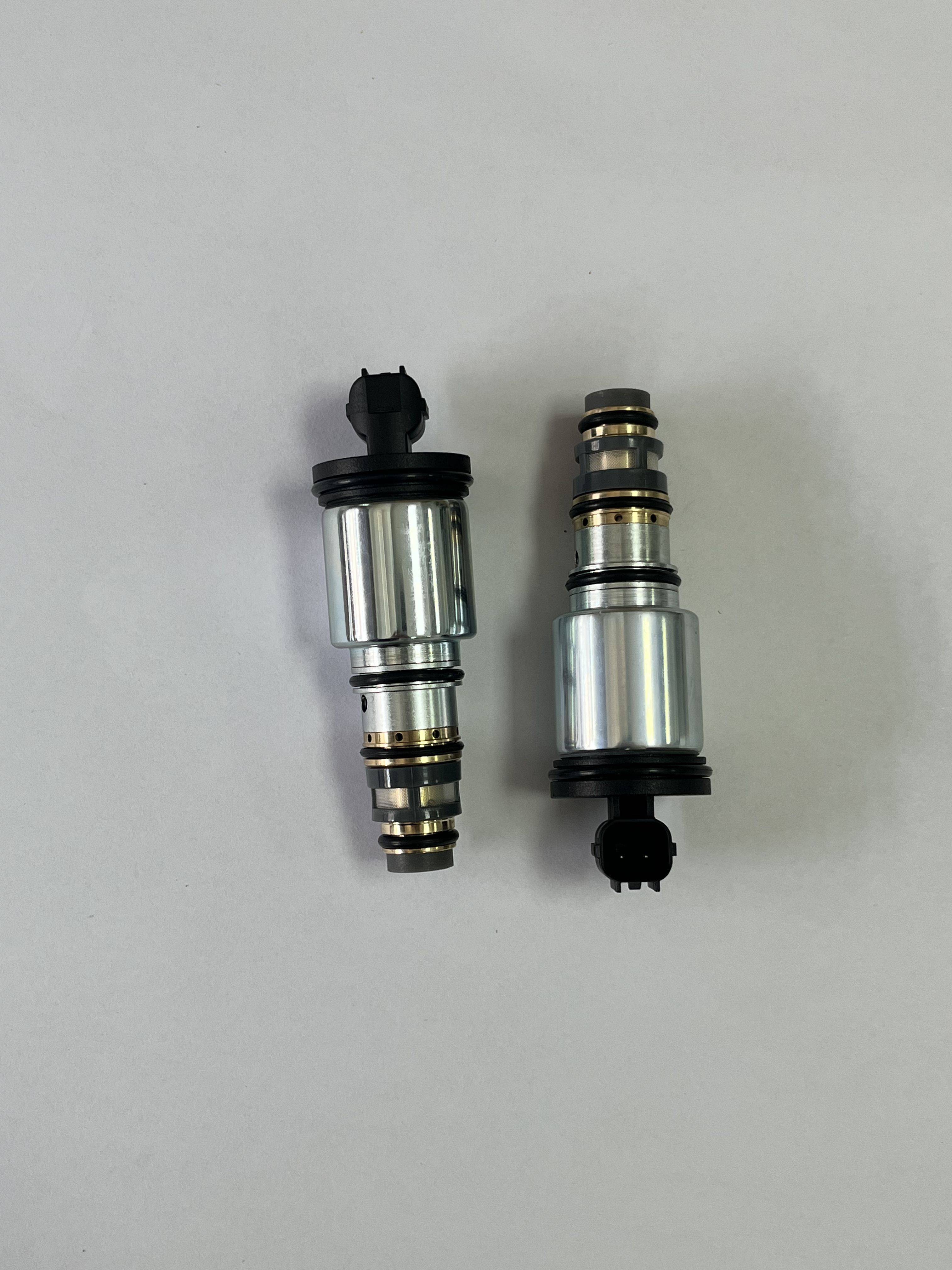
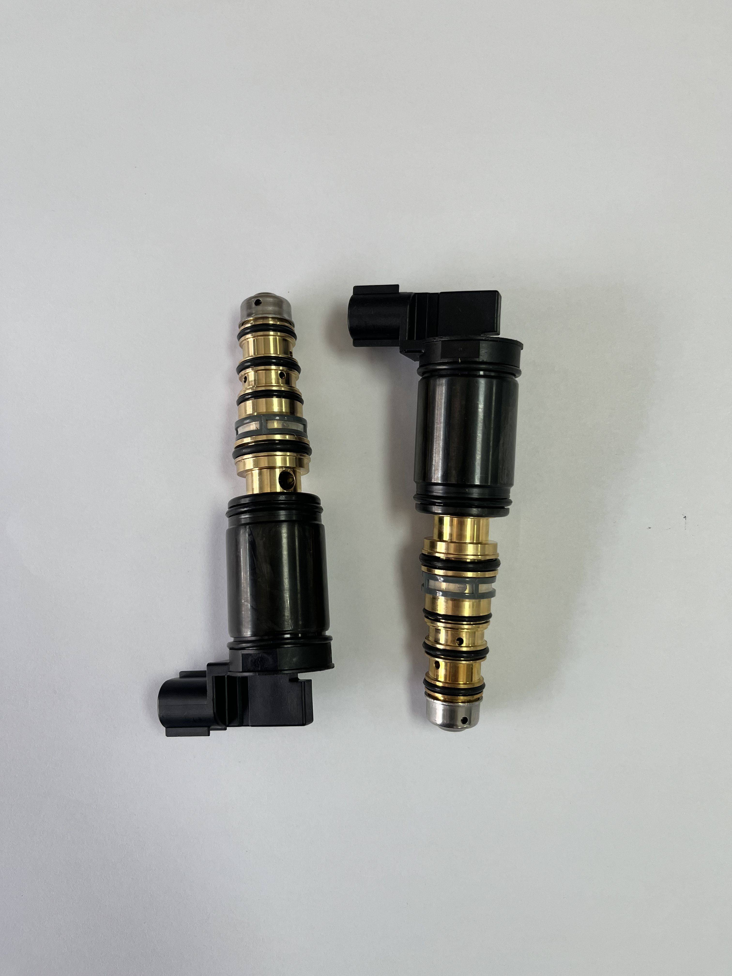
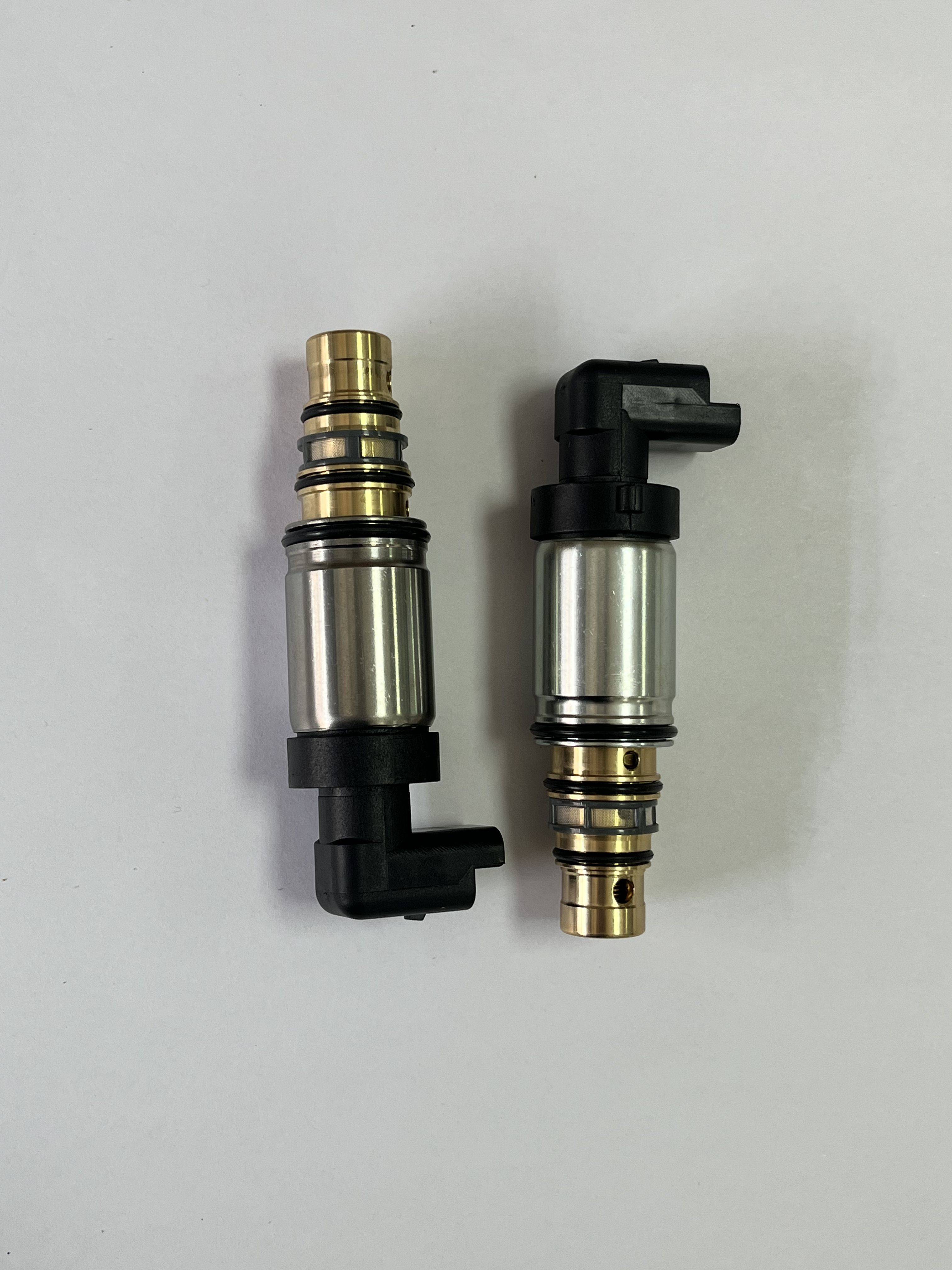
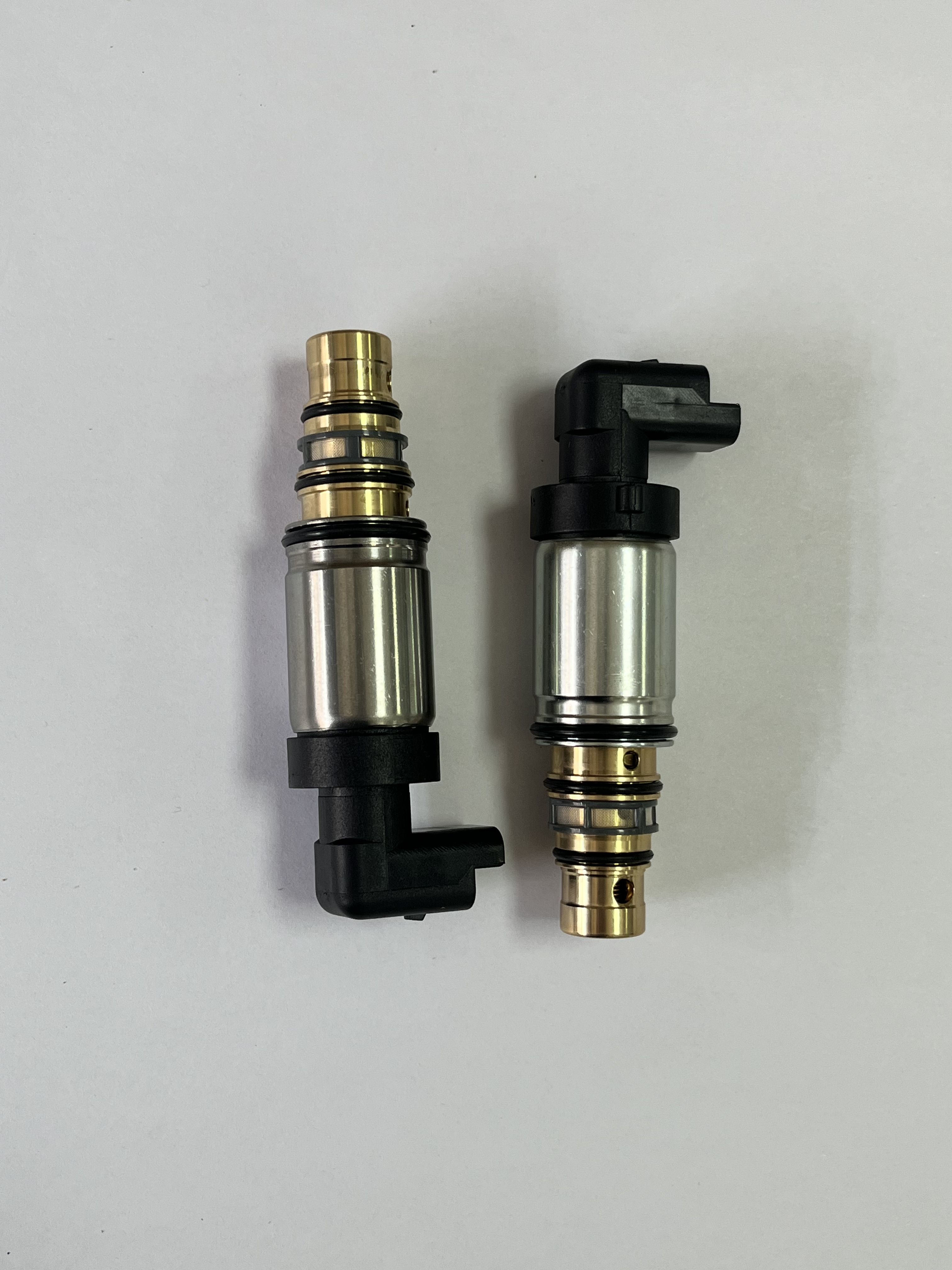
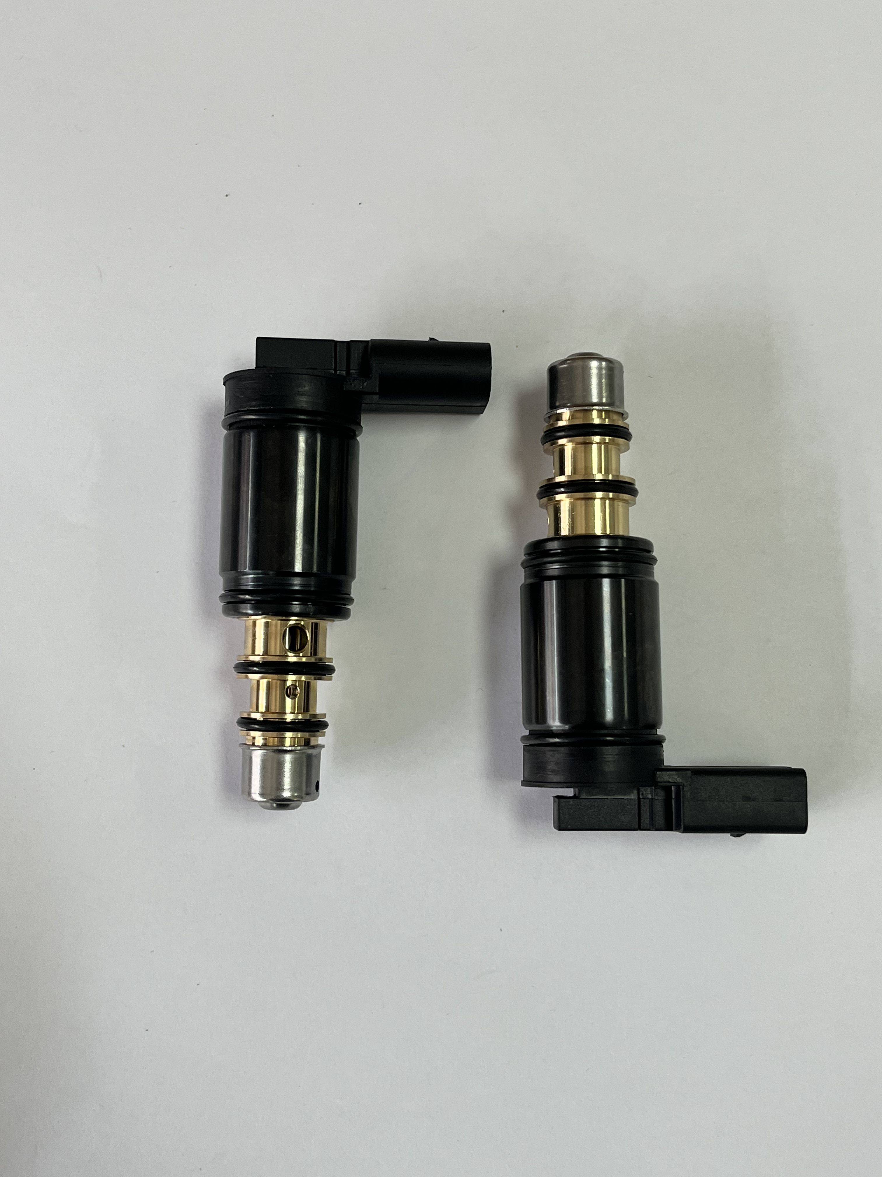
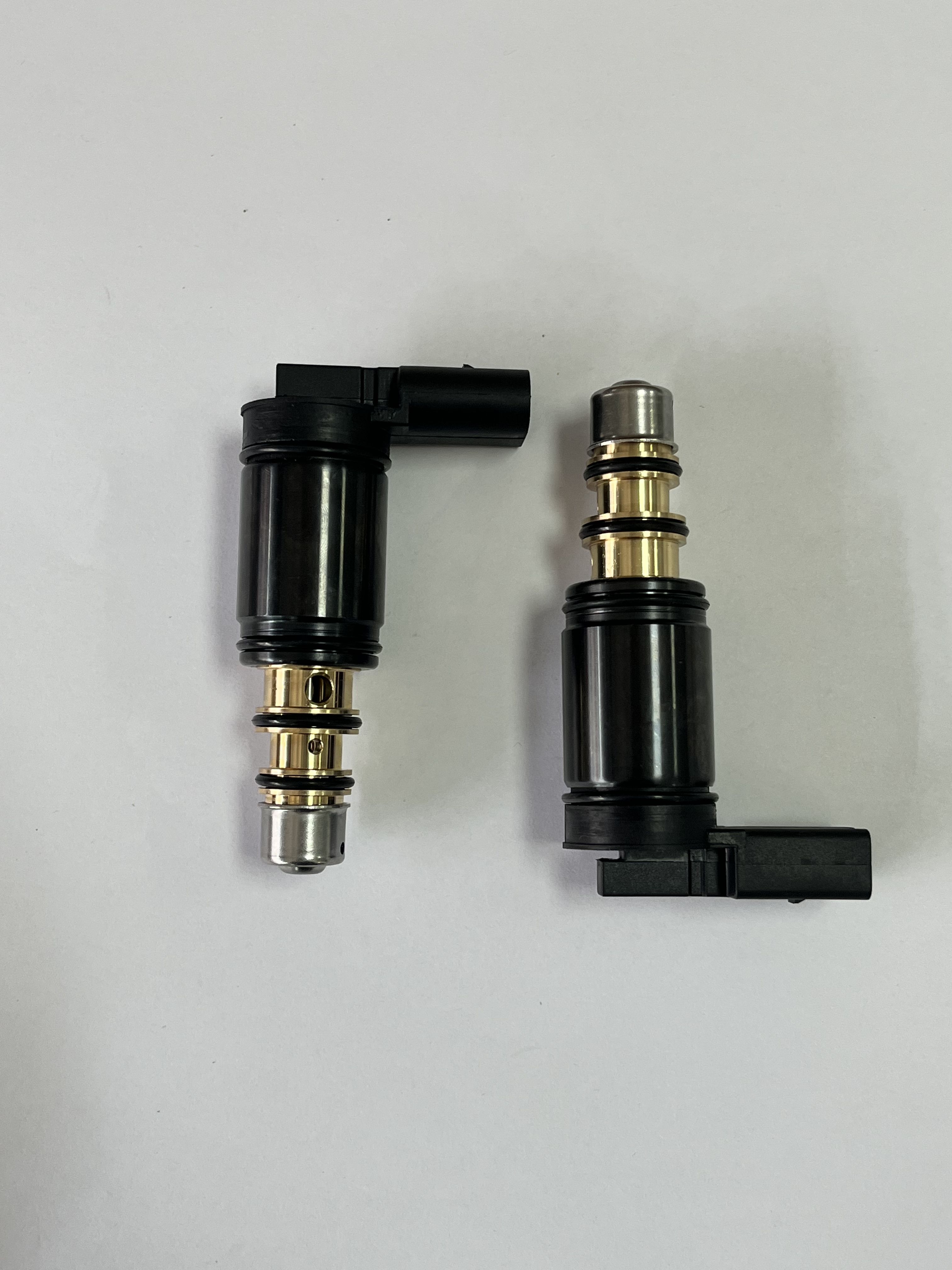
An A/C compressor flow control valve is normally used to regulate refrigerant flow or compressor displacement in an air-conditioning system, helping maintain cooling output while reducing unnecessary compressor load. However, the supplied product view does not clearly show a valve body. It shows two partially assembled circular electrical connector or cable-termination components with right-angle black housings, gold-colored exposed contacts, and multiple sealing rings. This distinction is important for buyers who need to prevent an incorrect part from entering an automotive or HVAC assembly line. The information below therefore describes the visible connector-style product and identifies the checks required before treating it as a compressor-control component.
Product Overview
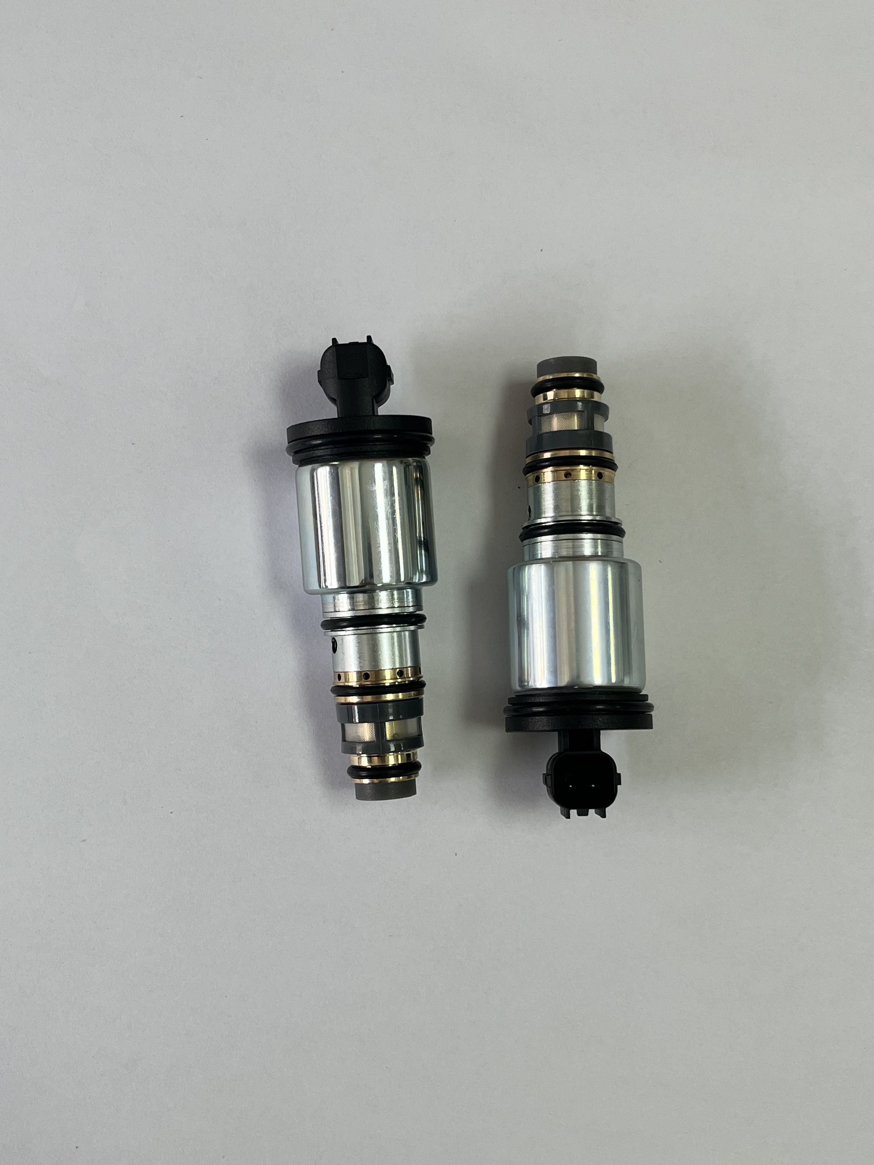
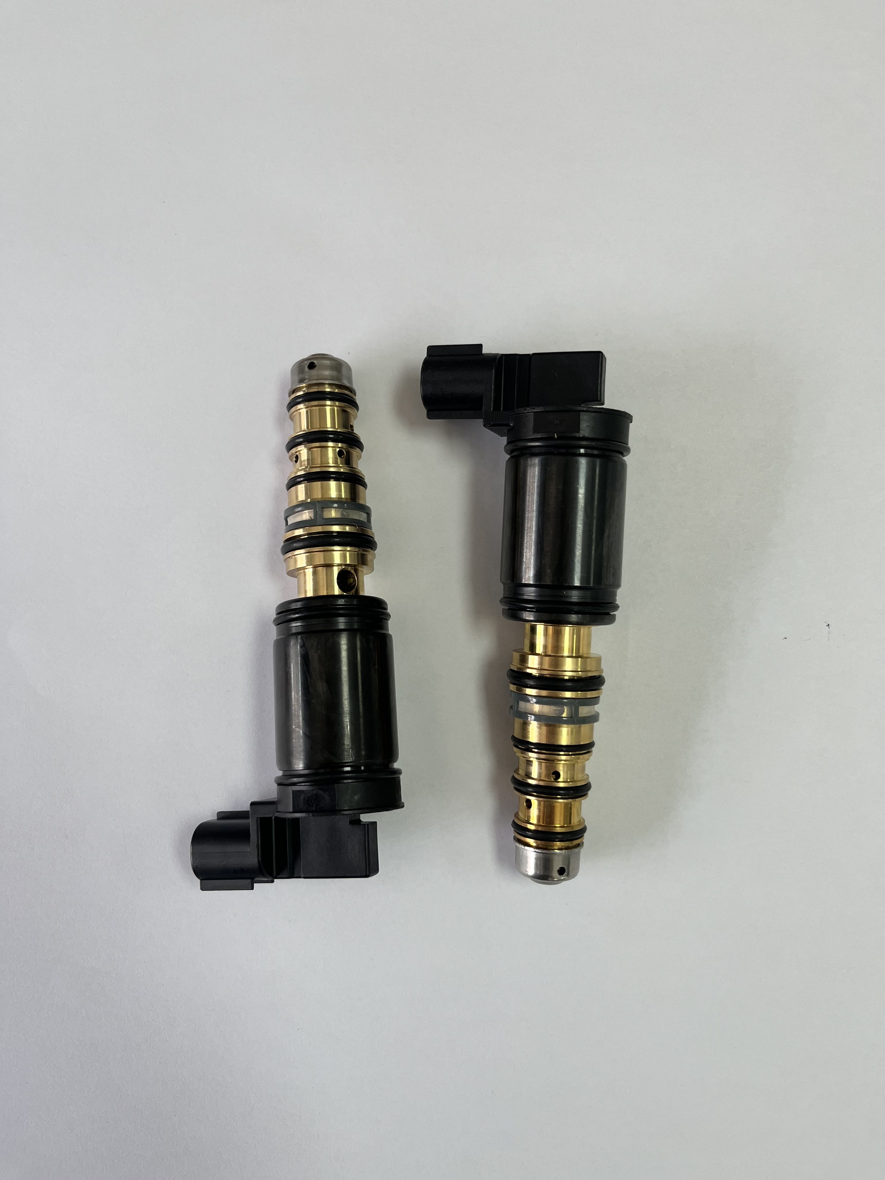
The pictured parts appear to be related electrical interconnect components, possibly mating variants or two stages of a cable-termination assembly. Each visible item has a stepped cylindrical form, concentric shoulders, retaining sections, and a compact right-angle cable exit. The black sections may serve as connector bodies, backshells, strain-relief features, or positioning elements. Their exact electrical interface cannot be confirmed from the image alone.
For a buyer searching for an air conditioning compressor flow control valve, the first technical question is whether the required part is an electromechanical refrigerant-control valve or an electrical connector used to connect a valve, sensor, or actuator. These are different products with different drawings, testing requirements, and installation procedures.
Visible Specifications and Capabilities
- Compact right-angle geometry suitable for installations with limited cable clearance.
- Stepped cylindrical bodies with visible retaining or alignment features.
- Gold-colored cylindrical contact sections, including visible cross-drilled or slotted details that may support conductor retention or fastening.
- Several black rings that appear to be elastomeric O-rings or sealing elements.
- Black molded-looking or machined-looking housing sections with external ribs or locking features.
No dimensions, circuit count, contact pitch, mating standard, wire size, voltage rating, current rating, temperature range, sealing class, or mechanical life are supplied. These values should be taken from a controlled drawing or supplier datasheet rather than estimated from the image.
Materials and Finish Options
The housing appears black, but its material is not confirmed. It could be an engineering polymer, coated metal, or a combination of materials. The exposed contacts appear to be a conductive copper alloy or similar metal with a gold-colored plated finish; the base metal, plating thickness, and plating system remain unknown. The black rings appear to be elastomeric seals, but the compound and temperature compatibility have not been provided.
For an automotive AC valve or other vehicle-mounted connection, buyers should specify the required seal compound, fluid or moisture exposure, thermal range, vibration environment, terminal plating, and corrosion requirements. For industrial instrumentation, connector keying, shielding, grounding, and cable-jacket compatibility may be more important than appearance.
Likely Manufacturing Process
Based on the visible geometry, production may involve precision turning of the cylindrical metal sections, drilling or slotting of contact features, surface plating, polymer injection molding or machining, seal molding, and final assembly. These processes are inferred from the image and are not confirmed manufacturing declarations.
A typical supplier review should include dimensional inspection of turned components, visual inspection of plating and molded housings, verification of seal placement, and a controlled assembly check. If the item is intended to connect to a variable displacement compressor valve, the mating interface and electrical pin assignment must be confirmed before production use.
Application Scenarios
Possible applications include equipment wiring harnesses, industrial sensors, control panels, instrumentation, automation systems, mobile machinery, automotive cable assemblies, replacement connector parts, and OEM subassemblies. The right-angle exit can help route a cable away from a crowded enclosure or compressor compartment.
The visible rings may support environmental sealing or component retention, but an IP rating or fluid-resistance claim cannot be made without test data. Likewise, the image does not prove suitability for refrigerant exposure, engine-compartment temperatures, pressure-control systems, or a specific HVAC compressor valve.
Quality Control and Documentation
Before approval, request a product drawing, connector identification, mating-part information, terminal material and plating specification, seal material, electrical ratings, operating temperature, and applicable inspection records. For a HVAC compressor valve assembly, also request the valve model, coil or actuator data, control method, refrigerant-system compatibility, and functional test requirements.
Incoming inspection can check visible damage, contact alignment, housing condition, seal presence, and key dimensions. Electrical continuity and insulation checks may be appropriate when the final circuit design is known. Do not substitute generic continuity testing for a validated valve-flow or compressor-control test.
Customization Guidance
Provide the supplier with the mating connector, cable diameter, conductor size, routing angle, available installation space, retention method, sealing target, and annual volume. A clear 2D drawing or sample mating component is especially useful because the exact connector type cannot be identified from the supplied image.
If the actual requirement is a variable displacement compressor valve, send the compressor make and model, valve mounting interface, electrical connector reference, control signal, refrigerant, and required operating range. If only the connector is required, specify whether the supplier must provide loose components, a terminated cable, or a complete harness.
Buyer Decision Factors
Confirm product identity before comparing price or delivery. A connector, HVAC control solenoid, and refrigerant flow-control valve may all appear in the same sourcing project but cannot be evaluated using the same criteria. Key decisions include mating compatibility, circuit configuration, sealing performance, temperature and vibration exposure, terminal finish, service access, documentation, and replacement availability.
Request a Technical Review
Contact the supplier with the image, application description, mating-part details, and required quantity. Ask for confirmation of the connector type and a technical datasheet. If your target is an A/C compressor flow control valve rather than the connector-style component shown, request a separate valve reference and do not approve the pictured item until its function, interface, and performance have been verified.