


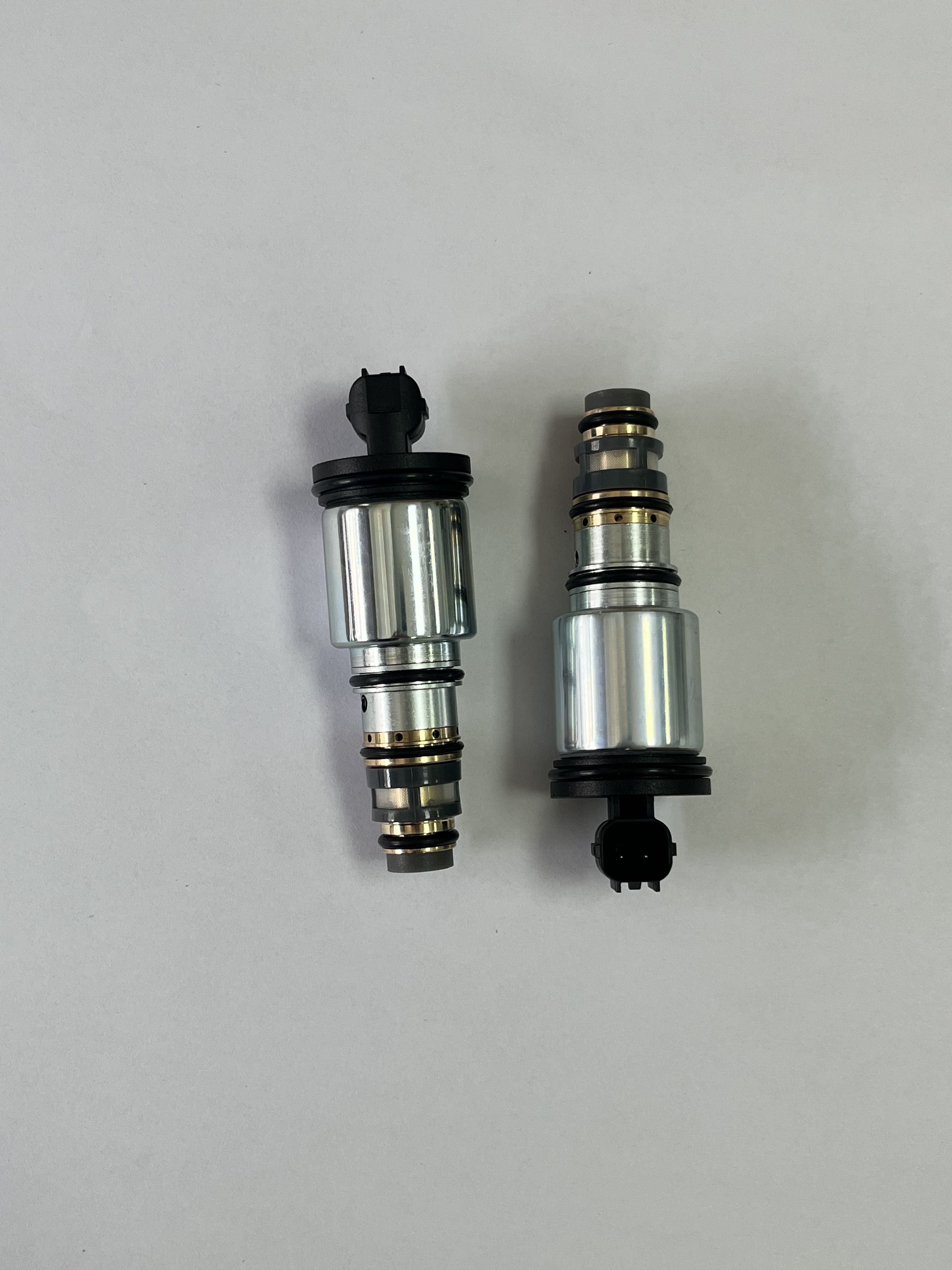
AC Control Valve Product Identification and Sourcing Note
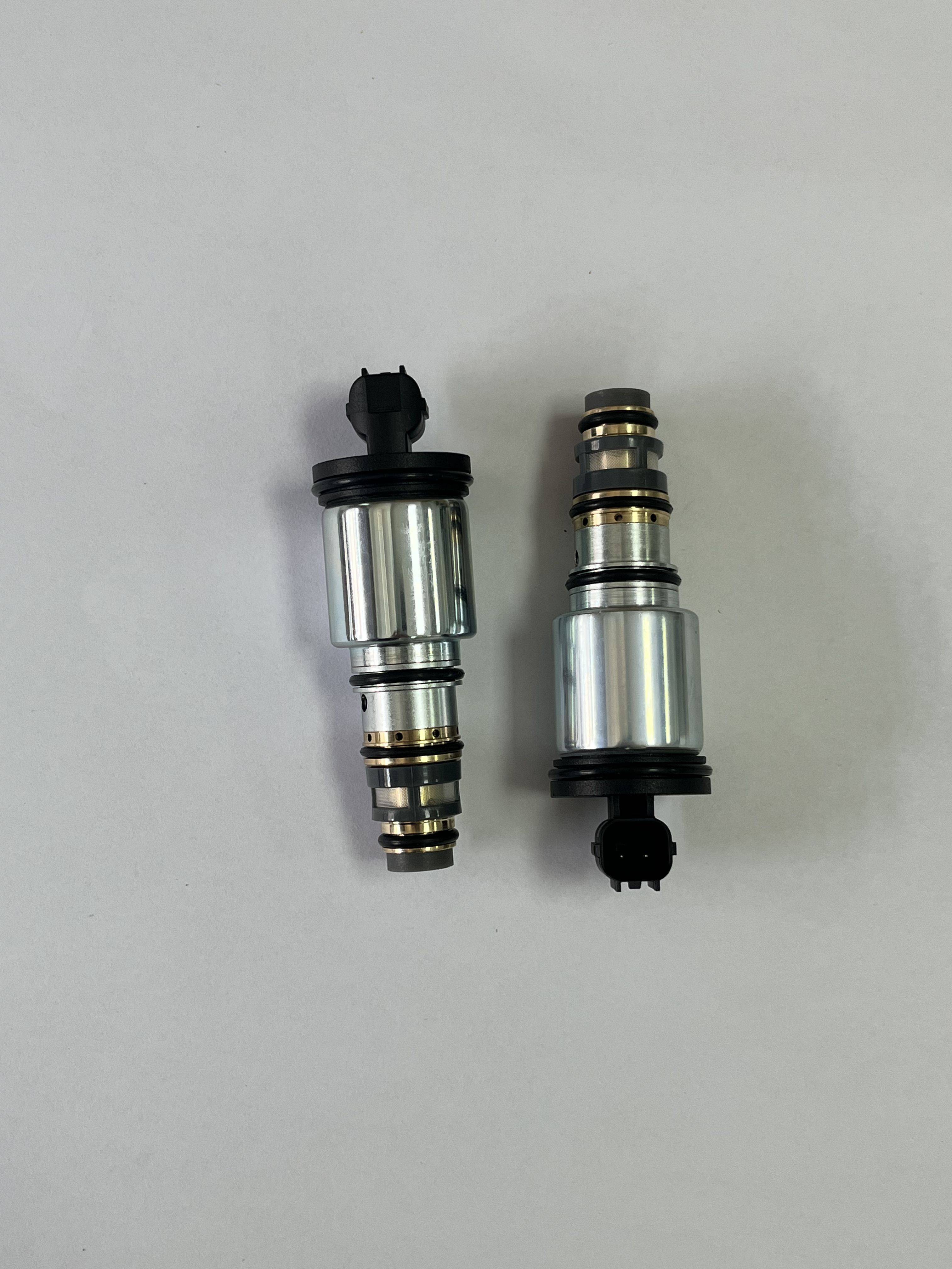
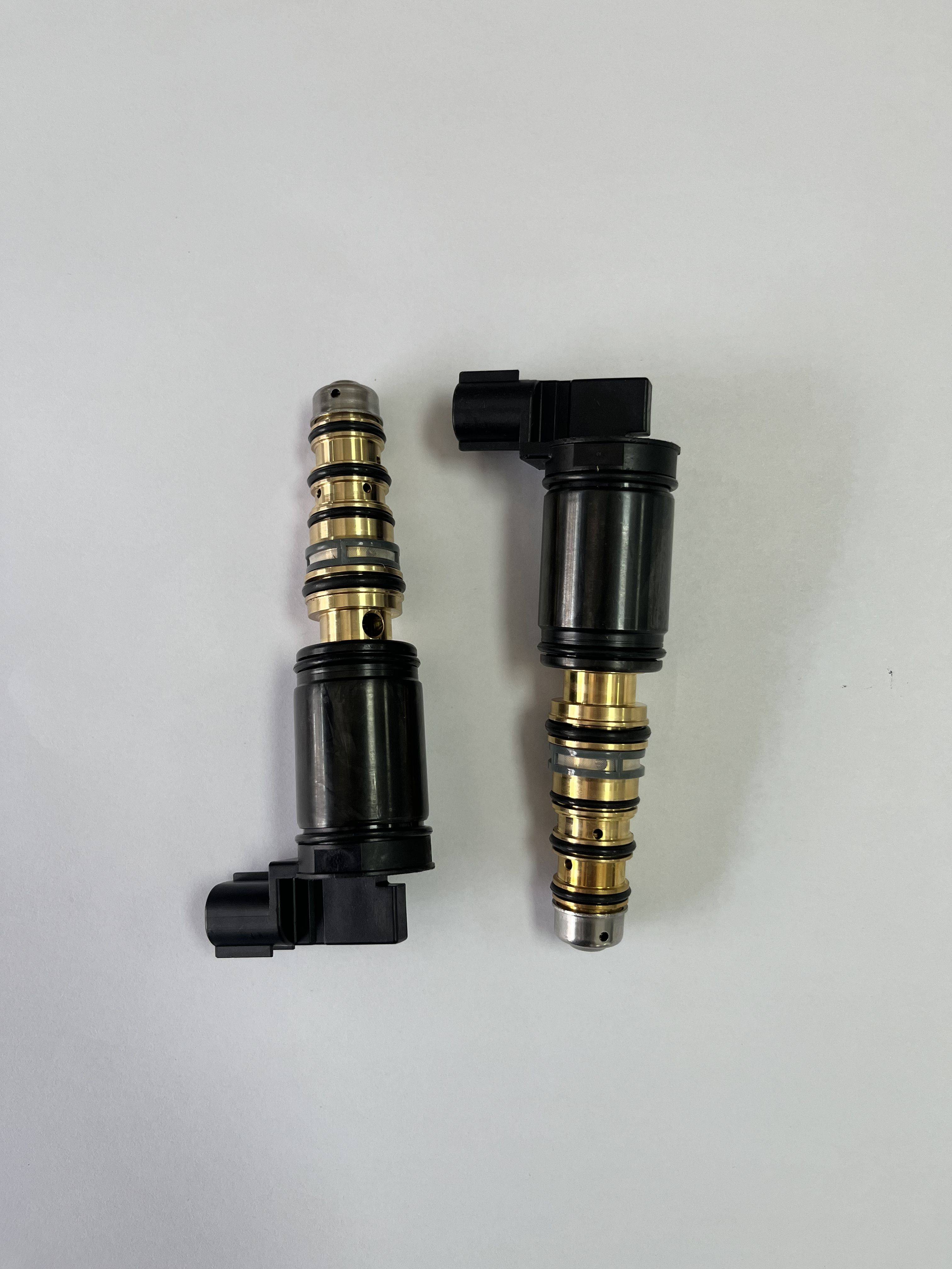
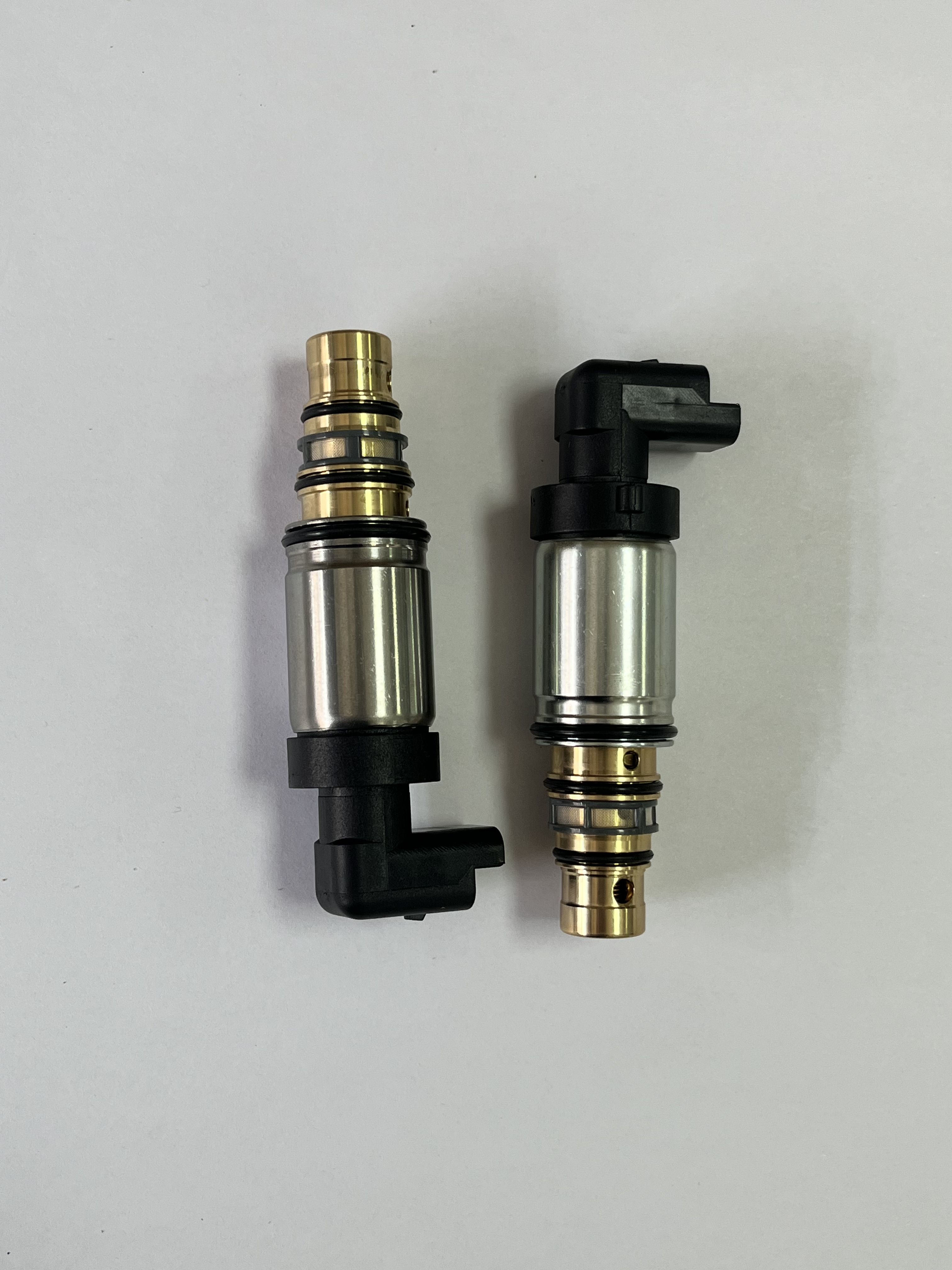
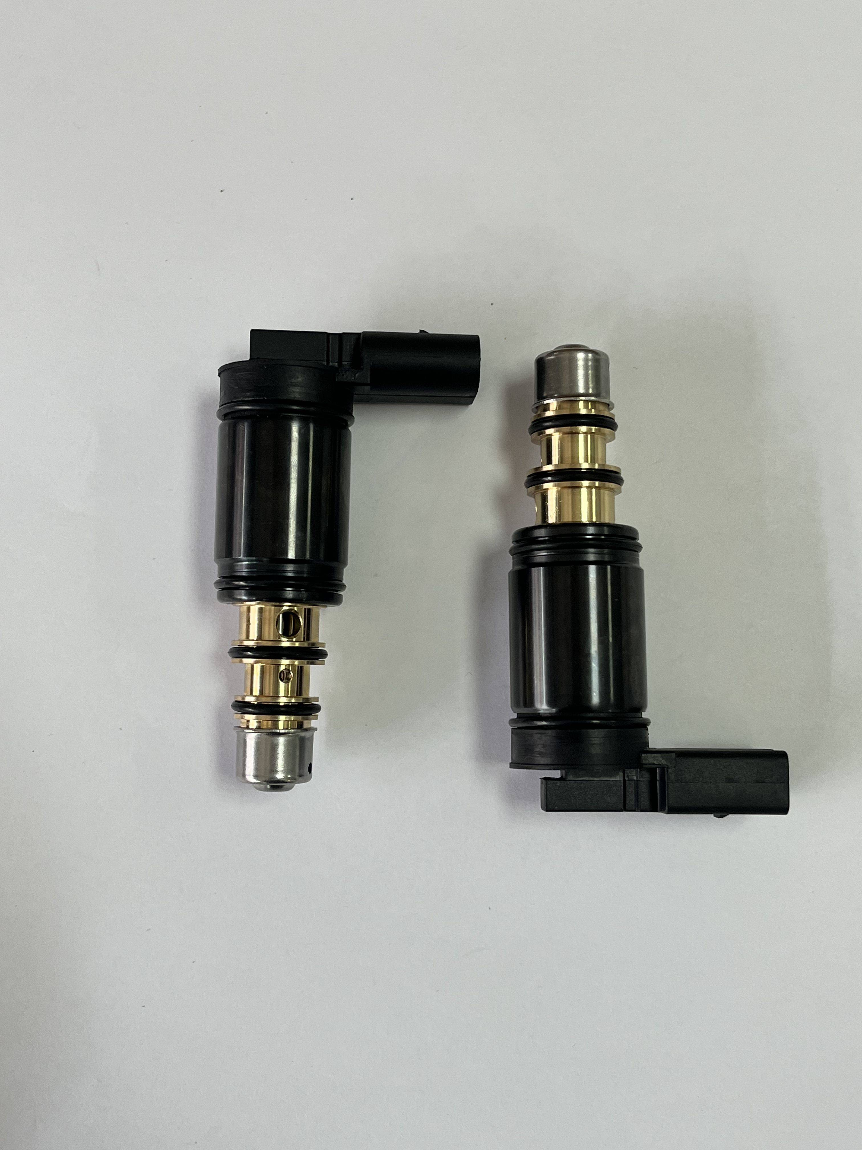
An AC Control Valve is normally used to regulate refrigerant flow or compressor capacity in vehicle climate-control systems, helping resolve unstable cooling, incorrect pressure control, or replacement needs during HVAC service. However, the supplied product image does not clearly show an air-conditioning valve. It appears to show two cylindrical electromechanical fuel-injector-like components with electrical connectors, sealing O-rings, and stepped metal bodies. Buyers should therefore verify the product category, application, and part number before treating these items as an Automotive AC Valve or other Car Air Conditioning Parts.
Product Overview
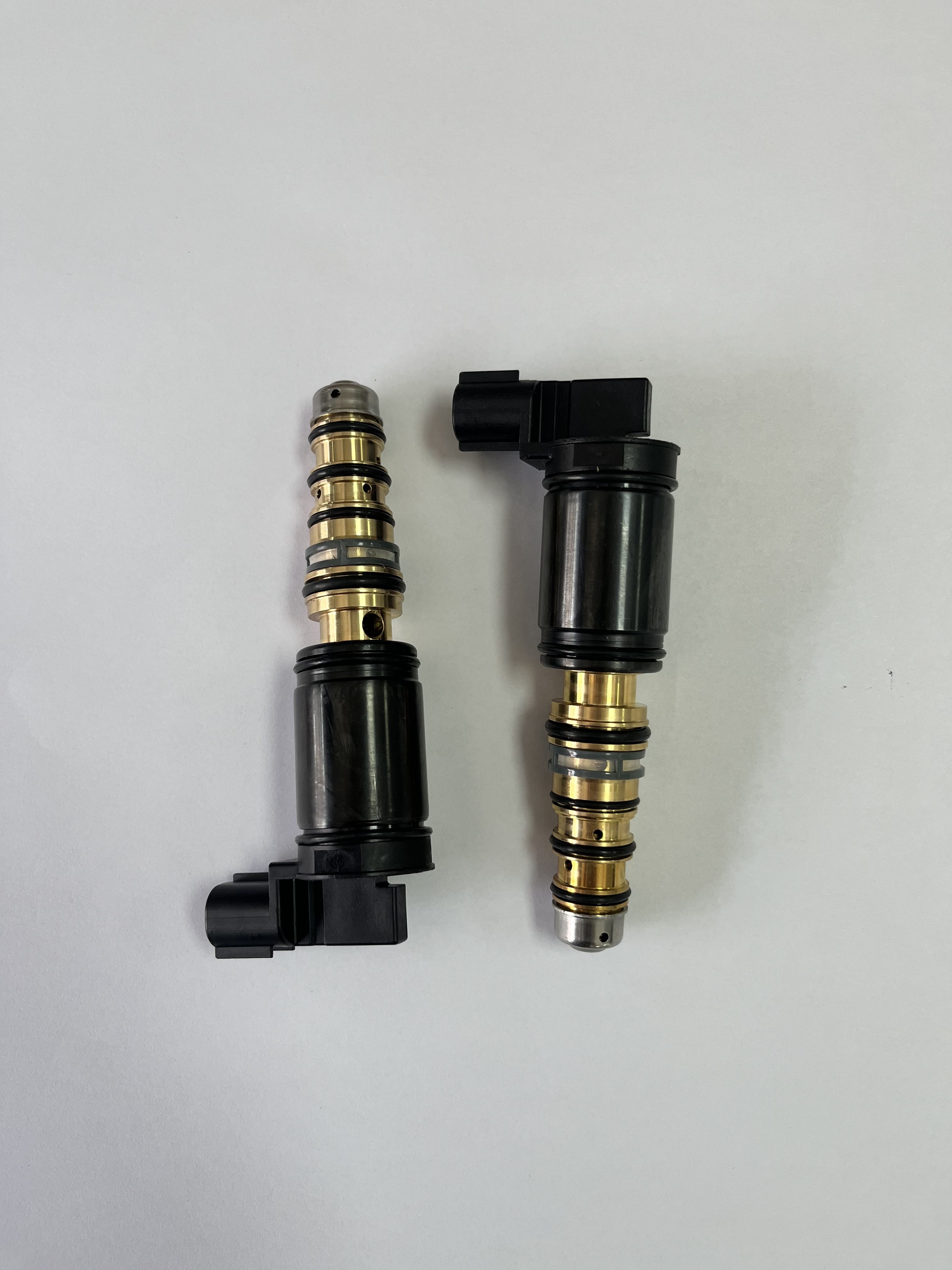
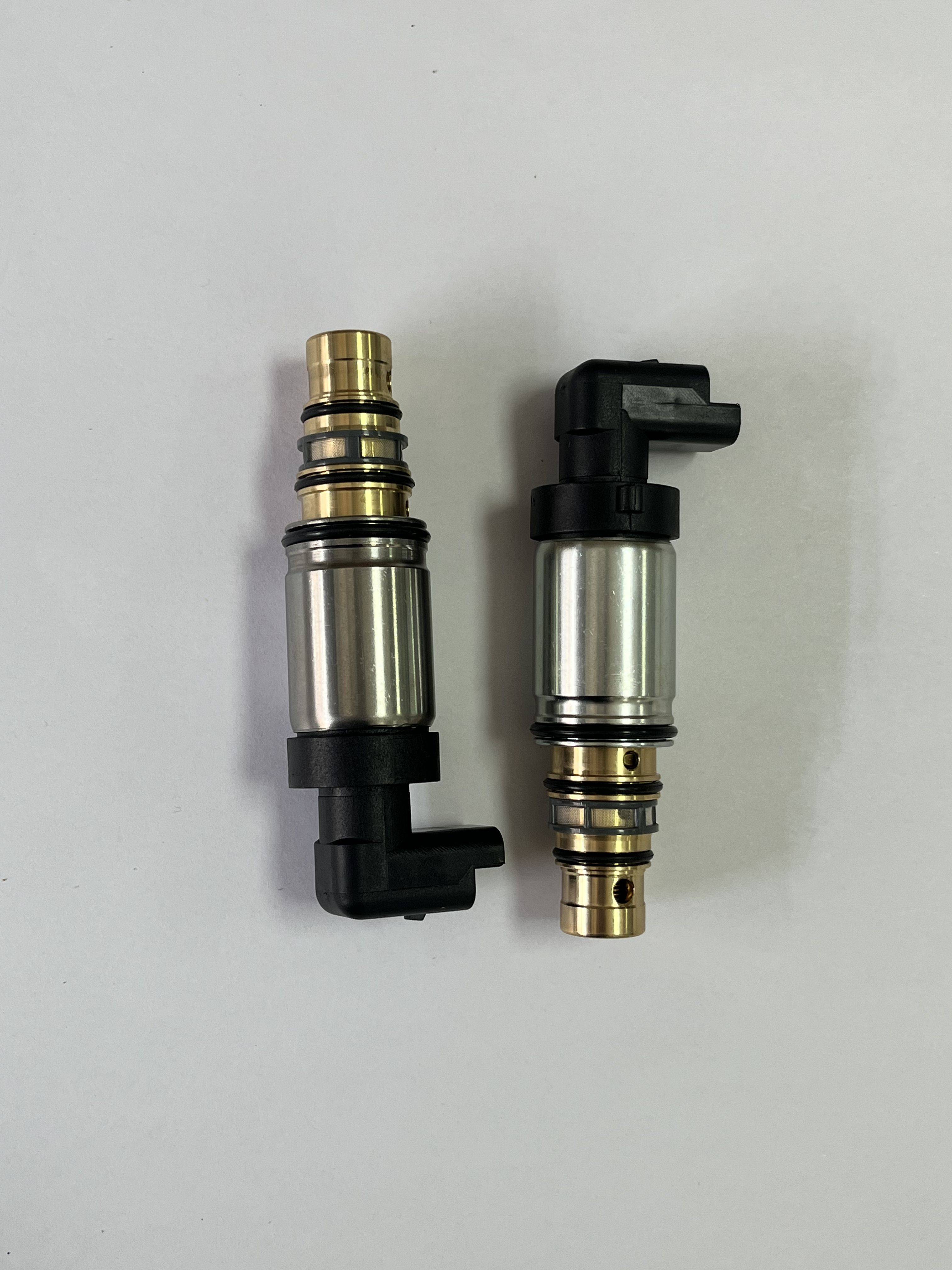
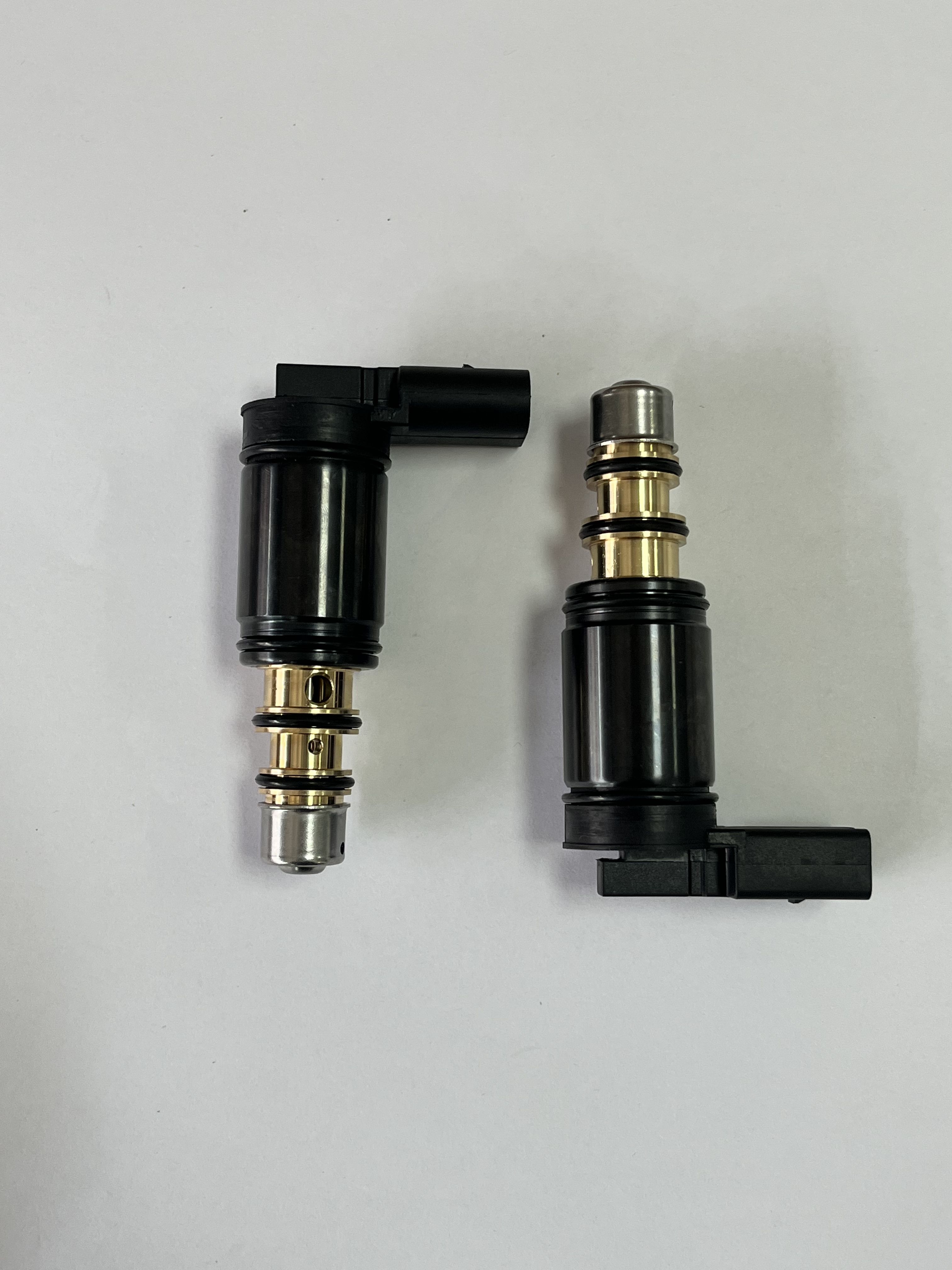
The visible components have an elongated cylindrical structure with several changes in diameter, raised shoulders, retaining collars, circumferential grooves, and black elastomer sealing rings. Their electrical plug housings include visible locating features and terminals, which is consistent with electronically controlled fluid metering components. One component also appears to include a fine metallic mesh screen, likely serving as an inlet filter, although its exact function cannot be confirmed from the photograph.
The image alone does not establish whether these are gasoline injectors, diesel injectors, LPG components, small-engine injectors, or another type of electronically actuated valve. It also does not confirm that the two parts are matching variants, opposite orientations, or components intended for the same assembly. This distinction matters because an injector and an AC Expansion Valve may both use an electrically controlled or metering-related design but serve entirely different systems.
Visible Specifications and Capabilities
- Cylindrical, stepped metal body with multiple diameter sections.
- Black molded polymer electrical connector housings with locating tabs and visible terminals.
- Several O-ring grooves and sealing locations for installation into a bore, rail, manifold, or similar interface.
- Reflective silver-colored metal surfaces that appear machined, formed, plated, or polished.
- Brass- or gold-colored rings and retaining sections visible on the assembly.
- Fine metallic mesh visible on one component, possibly functioning as an inlet filter.
- Small radial holes around one metal collar; their purpose is not confirmed from the image.
Important technical data remains unavailable. No verified dimensions, tolerances, flow rate, spray pattern, operating pressure, voltage, resistance, impedance, response time, leakage rate, connector pinout, or service-life information was supplied. These values should be confirmed through a technical drawing, sample inspection, or approved part documentation before purchase.
Materials and Finish Options
The visible bodies appear to use reflective silver-colored metal, potentially produced by machining, forming, plating, or polishing. The exact alloy and surface treatment are not identified. Black polymer is used for the electrical connector housings, collars, and related molded sections, while black elastomer O-rings and gaskets provide visible sealing interfaces. Gold- or brass-colored retaining elements are also present. Buyers requiring a specific metal, plating thickness, polymer grade, or elastomer compound should state those requirements during technical review rather than relying on appearance.
Manufacturing and Assembly Considerations
A component of this form may involve precision CNC turning or cold forming for the metal body, surface finishing, molded connector production, seal installation, mesh-screen insertion, and final assembly. These process descriptions are industry-based possibilities inferred from the visible construction, not confirmed production records for this item. A suitable supplier should be able to clarify the actual process route and explain how body dimensions, sealing interfaces, connector positioning, and actuation performance are controlled.
Application Scenarios
The visible design may suit replacement fuel-system components used in passenger vehicles, commercial vehicles, motorcycles, small engines, repair workshops, aftermarket distribution, refurbishment operations, or laboratory testing. Compatibility with gasoline, diesel, LPG, refrigerant, or any other fluid is not confirmed. For this reason, the product should not be substituted directly into Car HVAC Systems, a compressor circuit, or an AC TXV Valve application without positive identification.
Buyers searching for Auto AC Parts, Vehicle AC Replacement Parts, or an AC Repair Parts Supplier should compare the required system function with the photographed component. An actual AC Control Valve or AC Expansion Valve normally requires application-specific information such as refrigerant system design, compressor type, electrical control method, connection geometry, and vehicle compatibility. Those details are not visible here.
Quality Control and Verification
Before approval, request dimensional inspection of the body, groove locations, connector geometry, and sealing areas. Depending on the confirmed product category, relevant checks may include electrical continuity, resistance, actuation response, fluid leakage, flow behavior, filter installation, and seal integrity. No test results or formal standards were provided, so certification, emissions compliance, durability, and production validation must be confirmed separately.
Customization and Buyer Guidance
For an accurate quotation or sample review, provide the original part number, vehicle or engine information, intended fluid, connector details, installation dimensions, operating conditions, and required packaging. If the intended item is genuinely an automotive air-conditioning component, include the vehicle model, compressor or HVAC system information, refrigerant specification, valve location, and control requirements. A clear photo of the outlet, inlet, connector face, and mounting interface can help resolve whether the part is a fuel injector-like component or an AC system valve.
Request Technical Confirmation
Use this product as an identification and sourcing lead rather than a confirmed AC Control Valve specification. Contact the supplier with application data, drawings, samples, and compatibility requirements. The supplier can then confirm the correct product family, available materials and finishes, inspection scope, customization options, and whether the component belongs in Auto AC Parts or in a fuel-injection assembly.